Chunithm Ground Slider
This page lists details related to the official Chunithm Air Strings, taken off an arcade cabinet.
Contents
Sensors
The IR transmitters and receivers are Shinkoh Electronics P/N KB893, which have been discontinued.
Cable Harness Connectors
The items below are to mate with the stock harness.
Quantities listed below are for both sides.
Sensor Connector
- YLR-15V Qty 2
- SYM-01T-P0.5A Qty 26 (26-20 AWG) OR SYM-41T-P0.5A Qty 26 (20-16 AWG)
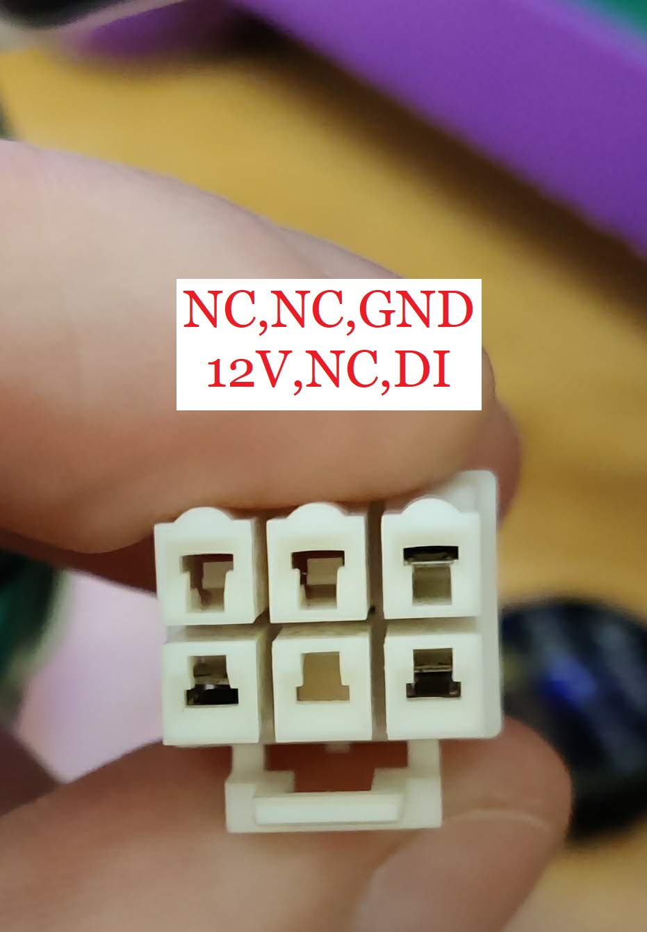
LED Connector
- YLR-06V Qty 2
- YLS-03V Qty 4
- SYM-01T-P0.5A Qty 6 (26-20 AWG) OR SYM-41T-P0.5A Qty 6 (20-16 AWG)
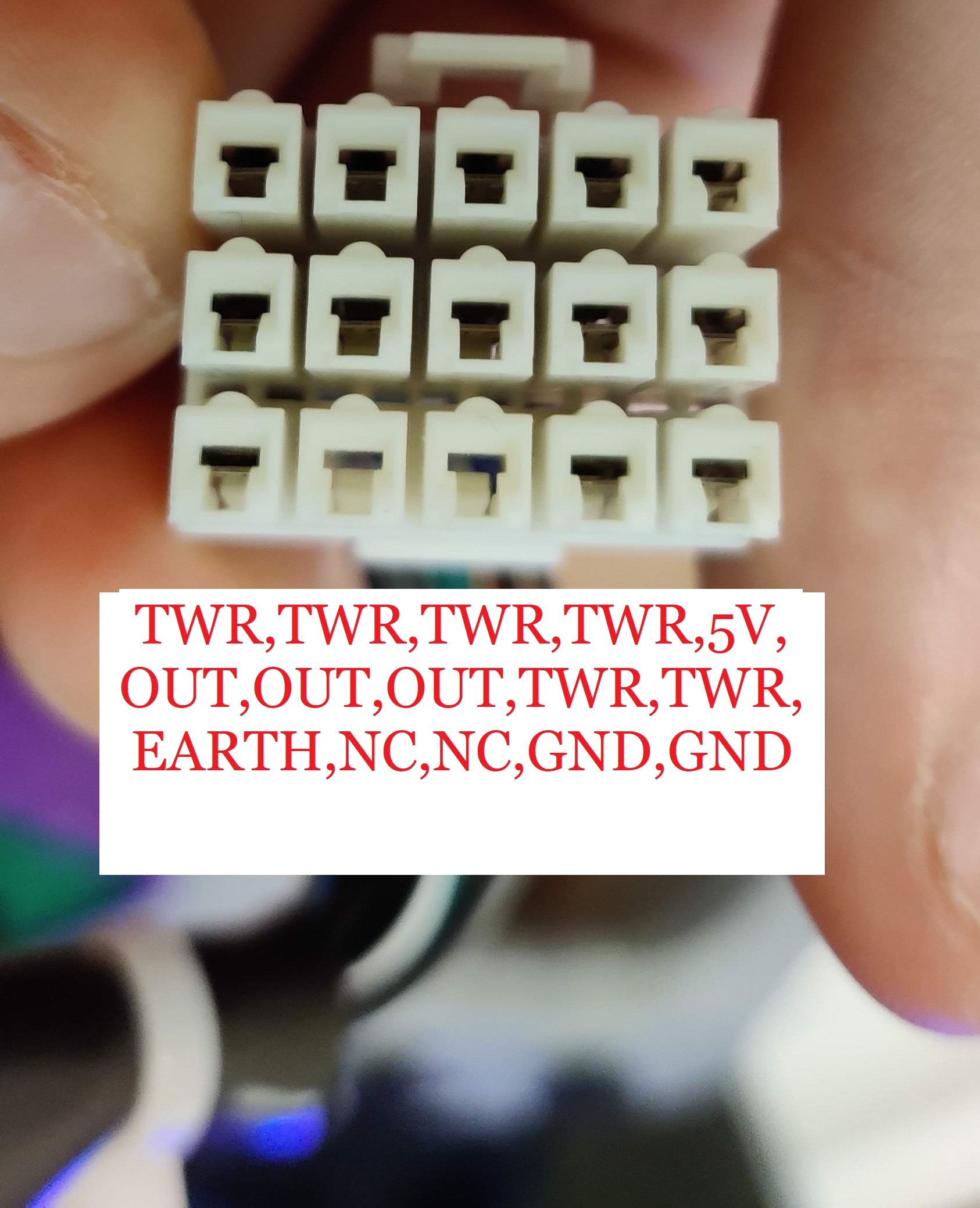
Pinouts
The outputs are split between the two towers, so each has 3. Starting from the lowermost beam to the uppermost beam, the order is as follows:
- Pin 8, right tower
- Pin 8, left tower
- Pin 9, right tower
- Pin 9, left tower
- Pin 10, right tower
- Pin 10, left tower
Note pin numbering is right to left, so pin 8 is the central pin of row 2, pin 10 the leftmost pin of row 2, and pin 9 is between them.
Using on a PC
To interface the Air Strings with your PC, consider the following board: https://github.com/Lemony0301/pcb-for-AIR_STRING
LED Strip
The LED strip is a 48 LED/meter 12V WS2811 strip.